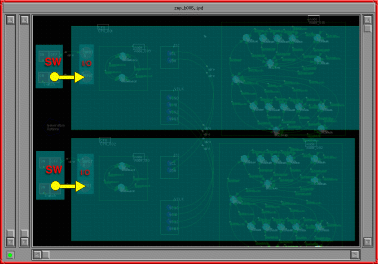
The switch components are used as external hardware mimics. While interactively debugging the system, the user can activate a switch component by clicking on it and the input component (connected to it) will see a switch toggle.
The I/O components generate events in response to input changes. These events are passed to any interested state machine for processing by the state machine schedular.
Other mimics such as LEDs are also availabel but not shown here. LED mimics change colour when a logic 0, 1 or high impedance is applied to them. They are normally connected to the output components of a CPU (not shown) or the outputs of some other component such as an I2C component.
I/O components are mapped directly into the I/O ports of the simulated CPU. When the simulated CPU writes to an I/O port the corresponding I/O components route the signals to other connected I/O components and can be subsequently read by other simulated CPUs during an I/O port read.
I/O components generates machine code which is directly executable in the target system. No additional debug code is generated for the target when the simulator is used in place of a real CPU.