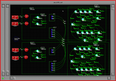
To view this image in greater detail click here
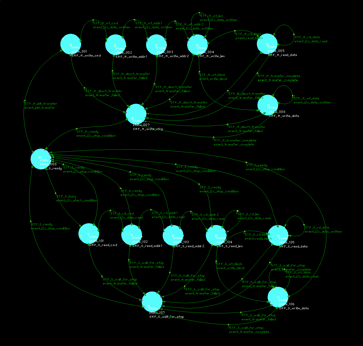
To view a component state machine in greater detail click here
To view a detailed description of the high level comms state machine (MODE B) click here
Each highlighted region is a functional block. Some functional blocks contain one or more other fucntional blocks.
This diagram shows that, at the highest level, the system is made up of two CPU components and four SW (switch) components (two groups of two).
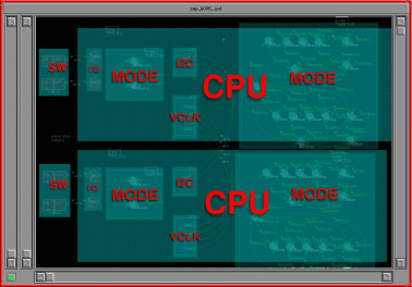
To view this image in greater detail click here
To view a detailed description of the high level comms state machine (MODE B) click here
Use this image as an index to this documentation, click on a functional block to see a description of that block