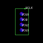
VCLK
The VCLK allows the generation of a system wide virtual clock. It allows several CPUs of varying speeds to be connected to a common free running clock signal. This clock ensures that all CPUs are never more than one virtual clock cycle apart.
A CPU with a VCLK component can opt into or out of the system wide virtual clock. By opting in, it ensures that it will keep pace with the rest of the system. By opting out, it enables the rest of the system to run at maximum speed. A CPU may continually opt in and out depending on its work load and impact on the rest of the system.
All CPUs with a participating VCLK component have an associated VCLK counter plus offset. The offset is imaginary and once the VCLK starts participating in the system wide virtual clock, the offset is fixed and remains constant. If the whole system is stopped at any time the difference between any two participating vclk counters (plus associated offsets) will never be greater than one.
The VCLK is driven by the state machine schedular as a background task.
When using the VCLK to synchronise message broadcasting, the software should wait for at least two VCLK cycles (the VCLK counter should change by two). This will guarentee that all other participating CPUs have seen the message.
Simulation Details
The VCLK object generates machine code which is directly executable in the target system. No additional debug code is generated for the target when the simulator is used in place of a real CPU. Signaling between different CPUs is performed by reading from and writing to real CPU I/O ports. The simulator uses XPUT objects mapped directly to the CPU's I/O ports to route the signals between simulated CPUs (see INPUT objects for further information).Code Generation
The VCLK object has several properies associated with it which are used to guide the code generator during the code generation phase. These properties are accessed via the VCLK settings object dialog.The properties are:
- VCLK Module ID
- VCG0 Port ID
- VCG1 Port ID
- VCG2 Port ID
- VCG3 Port ID
- Event To Generate
- Generate Event at Interval
Adding VCLK Objects To A Design
Normally a VCLK object is added to a design by copying it from the template window to the drawing window or from an existing VCLK object already on the drawing window. It must form part of a CPU if code is to be generated for it. This is done by placing it within the perimitor of a CPU object and using the VCLK objects add to group function or gather function to tie it to the CPU.Related Information
CPU objects
INPUT objects
WIRE objects
I2C objects
VCLK hardware description