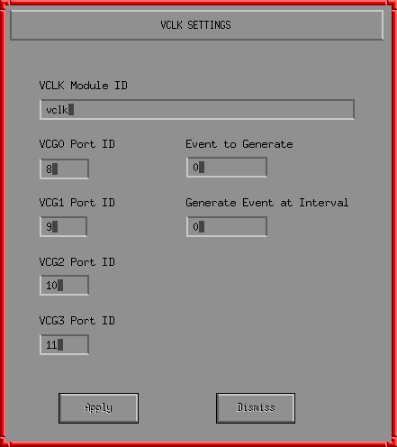
This picture shows the VCLK settings dialog.
This dialog pops up in response to selecting the edit VCLK menu option of an VCLK object.
The VCLK module name allows multiple VCLK modules running on the same CPU to be uniquely identified. It is therefor possible to use one VCLK module to drive the inter CPU comms and another VCLK module to drive other synchronus I/O
The VCG0, VCG1, VCG2 and VCG3 port IDs indicate the I/O bit to be used for that function (bits 0-7 are on PORT A, bits 8-15 are on PORT B). Once selected these ports are frozen for the generated code (they cannot be dynamically changed at run time in the simulated CPU). To change these ports the code must be generated again.
The value of the text field labeled "event to generate" is the event ID of the periodic event.
The value of the text field labeled "generate event at interval" is the periodic event reset value.
The VCLK can be used to generate a periodic event. The VCLK maintains a counter which it decrements each time a VCLK cycle is completed. The VCLK generates a periodic event when the VCLK counter reaches 0. The counter is then reloaded with the periodic event reset value. If this value is 0 or the event ID is 0 then no periodic event is generated.
All changed must be applied before the dialog is dismissed or they will be discarded.