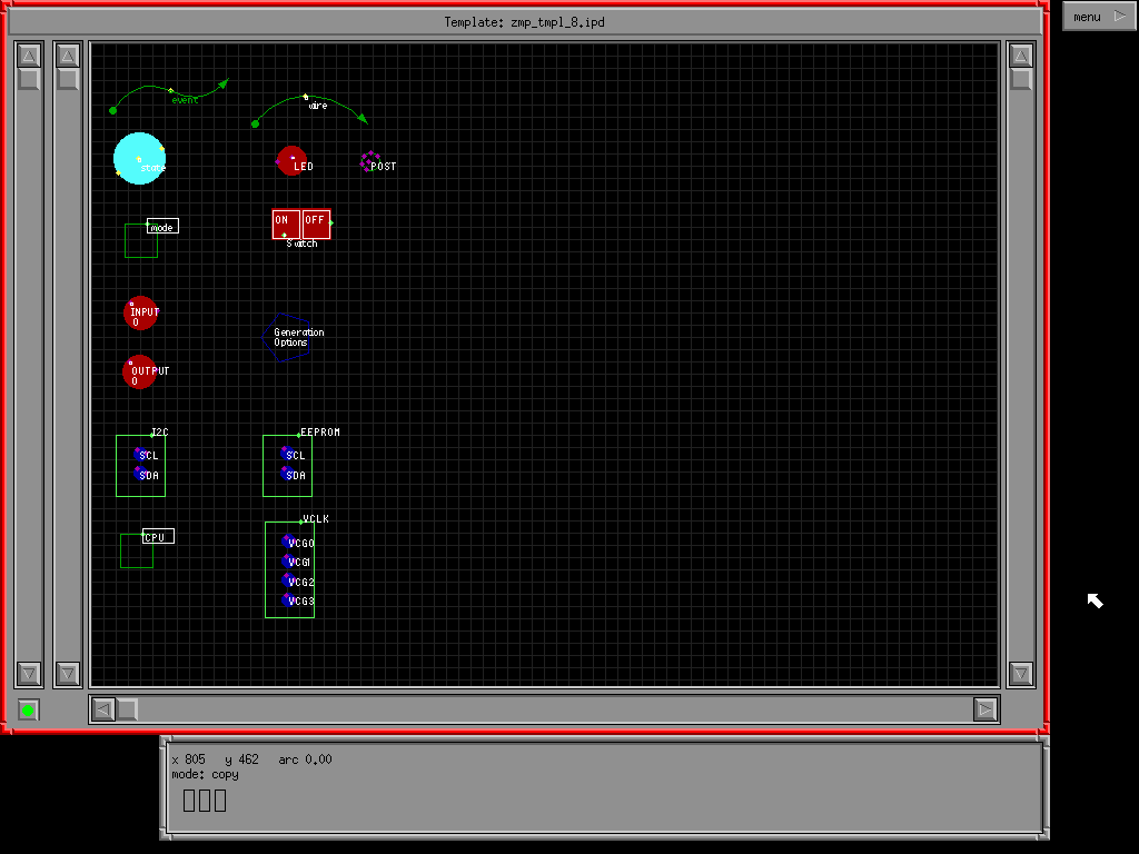
This picture shows the ZMech state machine component (template) window.
Objects are copied (simply dragged) from this window onto a work window.
This window is easily resized and positioned by the user to suite his/her
tast.
It shows:
-
event object (a state connector)
-
state object
-
CPU object (used to group together modes, I/O, VCLK and I2C into a single target executable
-
mode object (used to group together states and events into a state machine)
-
input object (brings the simulator CPU input out onto the diagram)
-
output object (brings the simulator CPU output out onto the diagram)
-
virtual switch (allows direct user input to a simulated CPU input)
-
virtual LED (allows direct feedback from simulated CPU output)
-
virtual wire (allows inputs and outputs to be tied together viaually without
the need to specify lists of connections)
-
post object (allows multiple objects to be tied together using multiple
segments of virtual wire)
-
I2C object (provides configuration interface to generated I2C code)
-
virtual EEPROM object (provids simulated eeprom device to which simulated
CPU can be connected)
-
VCLK object (provides configuration interface to generated VCLK code)
-
generation options object (provides interface to code generator to allow
some options to be configured via disgram)
