ZMech is an interactive state machine development tool and is an example of a CASE tool built using IPAD-Pro.
This document is intended to show how ZMech can:- be used to describe a state machine in a highly visual way
- easily translate a state diagram into a form suitable for direct execution by an embedded micro controller
- easily help you debug you state machine by actually running it against your diagram
ZMech comes with the 'C' source code for a small state machine event handler which can easily be compiled for your target embedded micro controller. It is this event handler that is actually run by ZMech while you are debugging your state machine through ZMech. So any changes you make to this event handler will be acurately reflected during your debugging of the state machine.
![]()
WARNING
this page is currently under review
Although this document describes a single state machine, ZMech is now capable of handling multiple interacting state machines simultaneously. The state machine described in this document should be viewed as an expanded components of a group of interacting state machines. Here is an animated demo of ZMech supervising the group while the user interacts with it.
The state machine described in this document was built and debugged using the ZMech state machine generator.
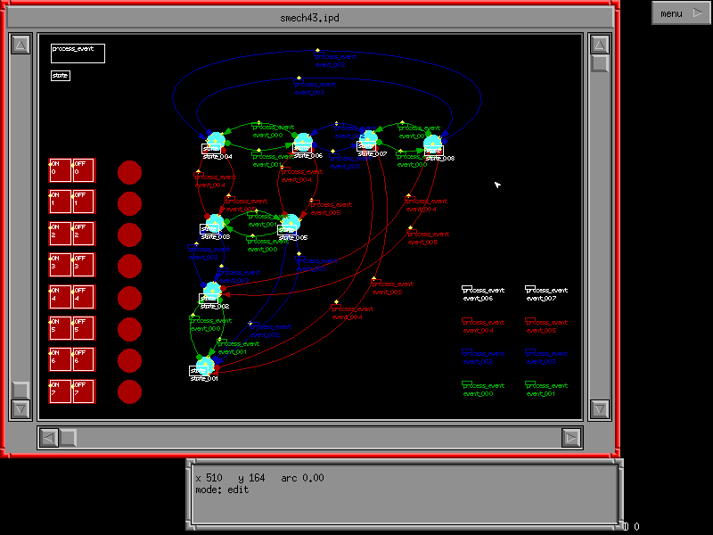
This state machine defines a priority encoder as might be used in a crisis monitoring system. Such systems monitor several levels of crisis and report on the highest level in effect at all times. In this instance there is a normal state and three levels of crisis (levels 0, 1 and 2 which map directly to the simulated inputs - see below).

This screen shot shows the state diagram for the priority encoder in the centre of the draw window. On the bottom left are 8 simulated inputs marked with on/off positions, next to these are 8 simulated outputs (they are actually solid red circles intended to represent LED's). While the state machine is being run clicking on the 'on' position of the simulated input will cause it to turn green indicating that the input has changed to a 1. Clicking on the 'off' position will cause it to turn red indicating that the input has changed to a 0. The simulated outputs will be red to indicate a 0 output and green to indicate a 1 output.
The text is deliberately made just big enough to read (if you look hard). This has the unfortunate effect of spoiling the diagram since it is too large for the diagram and spills over onto other features. But if it were any smaller you would not be able to read it. In practice you would tend to zoom in to sections of the diagram when working on it and pull out to get an overall view. Printing large complex drawings is also handled quite well by IPAD (and consequently ZMech). It is able to zoom into a drawing by printing it on several sheets (current zoom limitation on the evaluation version is 8 pages).
This state diagram has been coloured to help the user visualise groupings. The colours play no other part in this application.
Generating the state machine
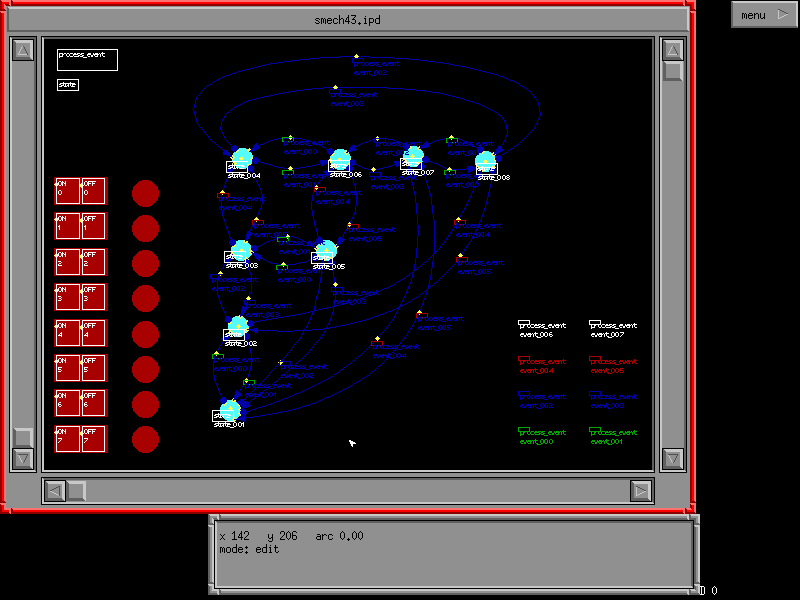
To convert the state diagram into a working state machine, select the draw window's menu and from it selecting 'Code' and then 'Generate'.This will cause the code generator to be invoked and a file containing the state tables to be generated. The state diagram will change colour to indicate the success or failure of the process on each of the component parts. Here we see that the generator encountered no problems as all the components of the diagram have been changed to blue

This is the state transitions table generated for this state machine, and these are the user supplied functions that the table refers to.
Once the code generator has successfully produced the state tables, the user switches to another screen or xterm and invokes make on the supplied makefile. This produces a dynamically loadable module which ZMech can load and execute. After generating this module the user switches back to ZMech and notifies ZMech that it should use the newly created module. This is done by selecting the draw window's menu and from it selecting 'Code' and then 'Reload DLL'
Now the user is in a position where he or she can execute the state
machine and trace the execution on the diagram. This is done by selecting
the draw window's menu and from it selecting 'Code' and then 'Run Mode'.
Running the state machine
Once in run mode the user can click on any of the simulated inputs and the inputs will be passed to the module that was built and loaded into ZMech for processing. The module is responsible for generating events from these inputs and will behave exactly as if the inputs had been read from a memory mapped peripheral device by a dedicated micro controller. It would be possible to run the state machine without the need to compile the module externally but by using the external module in this way we are actually testing the state machine as it will be compiled and dumped into a real embedded controller.While the state machine is being run, you will see the event that caused the state transition (if any) being highlighted together with the new state entered. On completion of a state transition, the state and the state transition link (the curve connecting two states) will change to grey. This provides a visual record of which event and state combinations have been checked. If after exhausting all events combinations any states or state transition links remain blue, then they are unreachable via the current state description. By watching the simulated outputs you will see exactly how the embedded controller changes its outputs in response to any changes to its inputs. An actual trace of this state machine is included here